-situ examination of ABB L-0
blade roots and rotor steeple of low-pressure steam turbine, using phased array
technology.
Proof-of-principle results.
This paper has been presented at
the 6th EPRI Steam Turbine/Generator Workshop and Vendor exposition - St Louis,
Missouri, USA - August 1999
Abstract
Two field trials on Darlington
unit #3 and #4 were performed in January and May 1999, for in-situ ultrasonic
examination of L-0 and L-1 blade roots and rotor steeples. The ultrasonic system
uses automated and manual phased array technology, capable of high-speed rate
and reliable detection and sizing. The system capability was demonstrated on 1:1
scale mock-ups and reference blocks, using EDM notches. Targets as small as 2 x
0.5 mm on steeple hooks and 3 x 1 mm on blade roots could be detected and
reliable sized. A custom built UT simulation software: Imagine 3D interfaces
with SIMSCAN to produce 1:1 2-D views and generates the spreadsheets with target
and probe coordinates and ultrasonic path and angles (refracted and skew) to hit
that target. The Ray-tracing simulated results were validated by experimental
measurements. Examination of L-0 blade and rotor steeple grooves was performed
with 2 phased array Focus systems under networking. Data analysis was done in
real time. Manual phased array was performed on L-1 blade roots (hook 1).
Special linear array probes were designed by OPGI and manufactured by Imasonic.
They performed very well during the 10-days examination period. Accuracy in
sizing is ± 0.3 mm for height, ± 1 mm for length. Location of indication in
2-D specimen layout is within ± 2 mm space envelope for blade root, and within
± 4 mm for rotor steeple. New developments under way will lead to a better
sizing and plotting, to an increase speed and to a reduced file size.
Representative results from the 2 field trials/examinations will be presented.
The system(s) will be full-speed commissioned by May 2000.
Introduction
 |
Darlington NGS and
Specialized Examination and Maintenance Department (SIMD) funded a
4-year project to build and commission an automated ultrasonic system
capable to in-situ examine ABB- type blade roots and rotor steeple
grooves of low-pressure turbine rotors (see Figure 1).
RD Tech- Québec-Canada developed
Focus phased array machine and associated software-Tomoview, based on
SIMD requests.
Imasonic-Besançon/France
manufactured the linear phased array probes (LPAP), most of them with
unique features (prototyping).
The feasibility study results were
published in EPRI Steam Turbine Workshop - July 1997-phase 1 (1),
and EPRI Phased Array Seminar in Portland – Sept. 1998 –
phase 2 (2). Since last fall, SIMD developed the new LPAP
with hard face and reduced contact area, built wing and steeple
manipulators, implanted more realistic targets and developed
examination procedures for different configurations.
Two field trials were performed in
January and May 1999.
Figure 1: L-0
blade (a), steeple (b), L-1 blade(c).
|
The January field trial objectives
were:
- test the RD Tech hardware/software under a long
examination period (10 days/10 hours/day)
- test the endurance of LPAP probes
- examine simultaneously with 2 Focus systems L-0
blade roots and L-0 rotor steeple grooves, spaced apart by 50-100 m (LP-1
and LP-3 rotors, and/or drive-end and non-drive end)
- test the prototyping manipulator for blade
– side examination
- test the prototyping manipulator for rotor
steeple
- analyze data in real-time
- get a production rate (5-7 minutes /file)
- produce daily report by the end of night shift
The May field trial / examination
objectives were:
- test the new hard-face LPAP
- test the new improved manipulators
- test the wing manipulator for L-0 blade
- test the acquisition performance of rugged
laptops
- combine manual examination with automated phased
array
- expend examination to L-1 blade root/steeple
- analyze data in real-time by 3 independent
analysts
- produce daily report by the end of the shift
- analyze all negative / positive aspects, in
order to improve the performance of the system(s) for the next outage- April
2000.
The paper will detail some aspects of
proof-of-principle examinations of low-pressure turbine components.
Reference
Blocks and Ultrasonic Equipment
Capability demonstration of phased array system
in automated and manual modes was performed on the following reference blocks
(see Table 1):
| Reference
block ID |
Nr. of EDM
notches |
Reference
target size
[ mm ] |
Remarks
|
|
L-0 Blade Roots
|
| RD Tech #3 |
36
|
3 x 1 |
T2 / Jan. 1999 |
| RD Tech #1 |
37
|
3 x 1 / 4 x 1.5 |
T1/T2 Jan. 1999 |
| Silver Blade |
34
|
5 x 1 |
T3 / May 1999 |
| SP-1 |
38
|
4 x 1.5; 3 x 1; 5 x 1 |
T1 / T2 Jan 1999
T3 May 1999
|
| SP-2 |
No targets
|
-
|
Comparison |
|
L-0 Rotor Steeple Grooves
|
| ABB Mock-up |
35
|
3 x 1; 4x1.5;
9 x 0.45; 9 x 1
|
Jan. 1999
May 1999
|
| Steeple Block |
39
|
3 x 1; 4x1.5;
9 x 0.45; 9 x 1
|
Jan. 1999
May 1999
|
|
L-1 Blade Root – Hook 1
|
| L-1 Block |
26
|
3 x1; 2 x 0.5; 4 x 2 |
Manual UT/ May 1999 |
| AC 878 |
5
|
3 x 1 |
Manual/Automated UT
May 1999
|
Table 1: Reference blocks for
capability demonstration of different techniques.
Ultrasonic equipment consists of the following
items:
- Focus 32/64 – O.P.G.I. – RD Tech
phased array ultrasonic machine
- Focus 32/128 – RD Tech – RD Tech
phased array ultrasonic machine
- MCDU-02- RD Tech motor controller drive unit
- XY – 01 manipulator- O.P.G.I. / RD Tech
L-0 / L-1 side/top inspection
- Steeple manipulator- O.P.G.I. design –
option 1 – Jan.1999
- L-0 universal manipulator- O.P.G.I. design for
both L-0 blade and steeple
- LPAP probes and holders- O.P.G.I. design /
Imasonic manufacturer (see Table 2)
- Tomoview 1.3R0- RD Tech software for acquisition
/ analysis
|
Probe ID
|
Fn / Nr. Elements/ Size
|
Type of wave
|
Remarks
|
|
2 / 2B
|
10 / 20 / 6x6 mm
|
L, T
|
L-0 Blade T3 –
May 1999
L-1 Blade T1 – May 1999
L-0 Steeple T2 – May 1999
|
|
3 / 3B
|
10 / 32 / 7 x 10 mm
|
L, T
|
L-0 Blade T1 –
Jan. 1999
L-0 Steeple T2 – Jan. 1999
|
|
3C – hard face
|
11 / 32 / 7 x 10 mm
|
L
|
L-1 Blade T1 - May 1999 |
|
5
|
5 / 32 / 10 x 32 mm
|
L
|
L-0 Steeple T2 - Jan. 1999 |
|
7
|
7 / 16 / 16 x 14 mm
|
L
|
L-0 Blade T1 - Jan. 1999 |
|
8 – hard face
|
11 / 32 / 4 x 10 mm
|
L
|
L-1 Blade T1 - May 1999 |
|
10 – hard face
|
12 / 16 + 16 / 5 x 5 mm
|
L
|
L-0 Steeple T2 - May 1999 |
Table 2: LPAP used in two field
trials / in-situ examinations.
SIMSCAN
/ IMAGINE 3D Simulation Results.
O.P.G.I. in cooperation with
UTEX Scientific and NDE Focal Point Technologies developed a simulation software
package Imagine 3D and SIMSCAN. The scope of this development was to validate
the focal laws, get the ultrasonic path, probe trajectory and refracted/skew
angles for different examination scenarios. The physical dimensions of LPAP were
incorporated into model. A 1:1 print display of 2-D with simulated UT rays was
also developed. The simulation data were validated by experimental results on
SP-1 blade, on reference blocks.
Figure 2 and 3 represents the
simulation displays of L-0 blade root (hook 1) T3, and rotor steeple (hook 5).
The results could be display into a spreadsheet and representative charts are
used for procedure development.
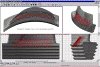 |
Figure 2: SIMSCAN results for T3-
CVX, L-0 blade. |
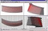 |
Figure 3:
Simulation results for T2, CVX L-0 Rotor steeple, hook 5.
|
An example of correlation between refracted angle
and probe movement is presented in Figure 4 and 5.
 |
Figure 4: SIMSCAN results for
refracted angles L-waves – T1 –L-0 blade-inlet-platform. |
 |
Figure 5: SIMSCAN results for
refracted angles T-waves on convex side, L-0 blade-hook 1 |
SIMSCAN / Imagine 3D were used to
optimize the probe trajectory for manual phased array /mono-crystal of L-1 blade
root inspection. The simulation results were incorporated into examination
procedures. SIMSCAN / Imagine 3 D provide examination layouts for all 3 objects
(L-0 blade, L-0 steeple, L-1 blade). An example of dependence of refracted
angles on probe position is presented in Figure 4a and b. More details about
ray-tracing simulation could be found in (3).
Ultrasonic
Results / Field Trial
The field trial from January 1999 was focused on
the following examinations:
L-0 blade root
- a combination of side and top raster scanning
with 2 LPAP, which could cover 125 mm from inlet and outlet
- the reference reflectors were: 3 x 1 mm for
top technique ( platform and 4 hooks)
- the reference reflectors were 6 x 1.5 mm for
side technique ( platform and 2 hooks)
- nr. of scanning files: 16, with a scanning
time of 5-7 minutes / file.
- cascade of focal depth to cover the range 25
mm – 125 mm (3-4 groups)
- size of T1 scanning file: 80 – 150
Mbytes
L-0 rotor steeple
- create 2 groups of focal laws for 2
different LPAP to compensate for manipulator rail off-set vs. concave/convex
sides radius
- run a line scanning on each side for both hooks,
from 120 – 360 mm
- the reference targets for Hook 1: 3 x 1 mm, and
for Hook 2 : 4 x 1.5 mm;
- nr. of scanning files = 2, with a scanning time
of 10 minutes / file
- two groups of focal laws to cover H1 and H2
depths
- size of T2 scanning file: 20 – 35 Mbytes
The ultrasonic results for probe 2, 3, 5 and 6 on
more than 30 targets concluded:
- detection capability: 2 x 0.5 mm in T2 mode
- detection capability: 4 x 1.5 mm in T1 mode
– range 25 – 50 mm
- detection capability: 5 x 1 mm in T1 mode
– range 50 – 125 mm
- sizing capability: 3 x 1 mm in T2 mode (± 0.5
mm for height, ±1 mm for length) – range 0 – 30 mm;
- sizing capability: 4 x 1.5 mm in T1 mode, range
45 – 125 mm
The proof-of-principle –
phase 2 from May 1999 was focused on "make-sense" inspection strategy,
expand manual phased array/mono-crystal examination to L-1 blade and improve the
quality of UT data, increase the productivity by using portable laptops for
acquisition, improve the manipulator’s performance (see Fig. 6), and use
hard-face probes. The following examinations were performed:
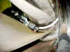 |
Figure 6: Wing manipulator- May 1999. |
L-0 blade root
- raster examination of 100 – 340 mm
on platform and hook 1
- reference reflector: 5 x 1 mm
- nr. of scanning files: 2
- scanning time: 5-7 minutes / file
- size of scanning file: 50 - 65 Mbytes
Examples are given in Figure 7 and 8.
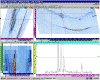 |
Figure 7: Detection of 3 EDM notches on
platform, L-0 blade, CCV side. |
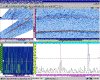 |
Figure 8: UT data analysis of an L-0
blade without defects – platform + H1 – CVX. |
L-0 rotor steeple
- line scanning from 50 mm – 440 mm
- reflector size: 9 x 0.45 mm for H1, and 9 x 1 mm
for H2, irregular shape
- nr. of scanning files = 2
- scanning time: 3-5 minutes / file
- size of scanning file: 10-15 Mbytes
Examples are given in Figure 9-12.
L-1 blade root
- manual phased array / mono-crystal for 0
– 40 mm, hook 1-concave side, inlet/outlet
- manual phased array for 60 – 120 mm, hook
1-convex side
- reference target: 3 x 1 mm
- use templates for probe trajectory
- use T-waves for better sizing
Examples are given in Figure 13-15.
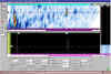 |
Figure 13: Detection of two EDM
notches on L-1 blade, at 20 mm and 40-mm depth. Manual P.A. |
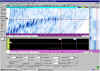 |
Figure 14: Sectorial scan
display of an L-1 blade without defects. |
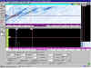 |
Figure 15: Length evaluation of
3 x 1 mm EDM notch, using T-waves. Manual P.A. |
Detection capability for T3, L-0
blade root is 3 x 0.5 mm. Targets as small as 9 x 0.15 mm and 2 x 0.5 mm could
be detected on H1-rotor steeple. Targets of 0.5 mm height could be detected with
an accuracy of ± 0.3 mm. Reflector length is measured with an accuracy of ±1
mm, and their location is within ±2 mm for blade roots and ±4 mm for steeple.
Conclusions
The field trials from January and
May 1999 proved to be successful. Significant improvements were achieved, and
the quality of examinations increased. More than 700 items were examined in the
critical areas. The combination between manual UT and automated phased array
produced reliable results, and a high productivity. Significant improvements
were identified, and corrective actions are under way. The ultrasonic results
proved the phased array examination has a redundant information regarding the
detection, sizing, and defect shape. The system(s) will be fully commissioned by
May 2000.
Acknowledgements
The authors wish to express their
thanks to O.P.G.I. – S.I.M.D., and DNGS management, for granting the
publication of this paper. One of the authors (P. Ciorau), wishes to express his
thanks to the following peoples: Alex Manukian and Gery Proulx- AEP-USA, Mike
Lundey and Phil Knox – Florida Light & Power-USA, for their support to
this project.
References:
A. Lamarre, N. Dubé, P.
Ciorau, and B. Bevins: "Feasibility study of ultrasonic Inspection using
phased array of turbine blade root" – 5-th EPRI Workshop Steam
Turbine/Generators – July 1997.
P.Ciorau, D. MacGillivray, A. Lamarre, and F.
Jacques: "Feasibility study of ultrasonic inspection using phased array of
turbine blade root and rotor steeple grooves-part 2" – EPRI Phased
Array Seminar-Portland, Sept. 1998.
D. Mair, P. Ciorau, D. Owen, and T.
Hazelton: "Ultrasonic Simulation – Imagine 3D and SIMSCAN. Tools to
solve the inverse problem for complex turbine components"- to be presented
to 26-th QENDE Annual Review of Progress July
25-30, Montreal, 1999.
Authors
Petru Ciorau,
Doug MacGillivray, Trek Hazelton, Lionel Gilham, Dale Craig – ONTARIO
POWER GENERATION Inc. ,Pickering – Canada
Jérôme Poguet - IMASONIC S.A. - France


