The Next Generation of X-ray Technology
For over 25 years, the internal structural integrity of tires has been confirmed using X-ray technology. Broken and crossed body ply cords, bad splices and chafer dimensions, belt step-offs, and material voids are common anomalies identified by tire X-ray inspection systems. A typical tire X-ray inspection system consists of four basic components: the X-ray generator, the tire manipulator or handling system, the imaging system, and the X-ray enclosure. Each component is essential to the function of the system; however, the type of imaging system makes it unique in the market.
 The purpose of the imaging
system is to acquire an image of an object and transmit the image to a user interface for
operator analysis. For years, the isocon low-light level imaging camera has been the
industry standard. X-ray imaging systems for tire applications originally consisted of an
X-ray source and an isocon camera coupled with a rare earth screen (see figure 1).
However, this imaging approach has drawbacks; such as, blurred images due to motion of the
tire, limited dynamic range, increased potential for geometric distortion, and relatively
slow image acquisition time. Image data is presented to the operator interface in standard
video format such as CCIR or NTSC.
The purpose of the imaging
system is to acquire an image of an object and transmit the image to a user interface for
operator analysis. For years, the isocon low-light level imaging camera has been the
industry standard. X-ray imaging systems for tire applications originally consisted of an
X-ray source and an isocon camera coupled with a rare earth screen (see figure 1).
However, this imaging approach has drawbacks; such as, blurred images due to motion of the
tire, limited dynamic range, increased potential for geometric distortion, and relatively
slow image acquisition time. Image data is presented to the operator interface in standard
video format such as CCIR or NTSC.
About eight years ago, a new image detector, the linear diode array or LDA, entered the market for tire inspection. Compared to other tire inspection systems, the LDA cuts inspection time by two thirds by inspecting the entire tire in a single revolution. The geometric distortion caused by projecting the image of a round tire onto a flat screen or camera is also reduced because the LDA’s imaging head wraps around the tire being X-rayed. Linear diode array technology produces an image with superior dynamic range in comparison to other imaging systems. The image data is presented to the operator interface in a digital format, which enables easy image storage.
The first LDA systems that emerged were very hardware specific. They were based on a VME bus structure. Proprietary circuit boards were needed specifically for the system. Basically, the unit consisted of three separate imaging systems. Each imaging system consisted of the detector array, computer interface board, host computer, and a manual/PLC (programmable logic controller) interface. These imaging systems encountered problems with decreased reliability and increased installation and routine maintenance time.
Today, LDA technology has entered a new era. A technologically
advanced linear diode array imaging system, LDA 2005, has recently entered the market. The
LDA 2005 is controlled by a high powered industrial PC-based system. Its imaging system
consists of a scanner head, a processing unit, and an MMI (man/machine interface) user
interface. It can be controlled remotely during automatic sequences or from the user
interface in 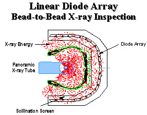 manual mode.
The high-resolution LDA system consists of an array of photodiode modules totaling 1536 diodes. Each module contains groups of 64 diodes laminated with a scintillation screen to create X-ray sensitive diodes. The scintillation screen converts the photon energy emitted by the X-ray tube into visible light on the diodes. The diodes produce a voltage when the light energy is received. This voltage is amplified, multiplexed, and converted to a digital signal (see figure 2).
Scanning a rotating tire between the X-ray source and the diode arrays forms images. X-rays are projected through the tire and received by a single row of diodes. The diodes collect energy for several milliseconds to integrate the signal. When the integration time is expired, data is read from the diodes by the interface board and sent to the computer. Diodes are reset and ready to receive X-rays for the next line of the tire to be scanned.
 In contrast to early LDA systems, the LDA 2005 gathers raw 12-bit
digital data that enters the Host PC from the data acquisition interface board. Data
acquisition software corrects the incoming data for pixel-to-pixel variations in diode
sensitivity. The data is then displayed as an image to a trained operator (see figure 3).
In contrast to early LDA systems, the LDA 2005 gathers raw 12-bit
digital data that enters the Host PC from the data acquisition interface board. Data
acquisition software corrects the incoming data for pixel-to-pixel variations in diode
sensitivity. The data is then displayed as an image to a trained operator (see figure 3).
The LDA 2005 has made possible many enhancements that affect overall performance of the tire X-ray inspection unit. Primarily, the high powered industrial PC that controls the LDA 2005 has contributed to the flexibility of the inspection system. It enables rapid processing and image analysis. Proprietary system software maximizes the potential of each LDA detector.
As stated earlier in this paper, one of the unique characteristics of the LDA is that it has an excellent dynamic range. This means that it is capable of generating useful data when X-raying both very thick (tread) and thin (sidewall) sections of the tire simultaneously. However, the human eye is capable of visualizing only a small fraction of the LDA’s full dynamic range. To compensate for the limitations of the human eye while still taking advantage of this feature of the LDA, a variety of selectable contrast and brightness enhancing tables are available.
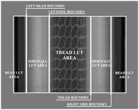 Commonly called Look-Up Tables, their function is
typically to raise the average brightness level in very dark areas of the image and
enhance the contrast in very bright areas. Additionally, these look-up-tables can be
applied at user definable boundaries (see figure 4). That means, for example, that the
bead area, sidewall, and tread can each have their own unique level of enhancement.
Commonly called Look-Up Tables, their function is
typically to raise the average brightness level in very dark areas of the image and
enhance the contrast in very bright areas. Additionally, these look-up-tables can be
applied at user definable boundaries (see figure 4). That means, for example, that the
bead area, sidewall, and tread can each have their own unique level of enhancement.
The proprietary software also decreases routine maintenance. The LDA 2005 software can scan each diode on the LDA to verify its performance. An operator can run daily system diagnostics to guarantee an accurate inspection sequence 100 percent of the time.
Another benefit of a PC-based system is simplified image storage. The operator can digitally save an acquired image to a floppy diskette or the Host PC’s hard drive. Further development has allowed for composite bead-to-bead images to be output to a 1200 DPI laser printer. These options simplify archiving images for future reference.
Traditionally, array-based systems have presented a tire image as three images on three monitors: the upper sidewall, the tread, and the lower sidewall. The LDA 2005 PC-based system presents a composite view of a complete tire on a single monitor. Due to this enhancement, image analysis is simplified and cycle time is reduced. Installation and maintenance is minimal and operator fatigue is greatly reduced. Currently, a 1600 X 1280 high-resolution 29" monitor, based on military specification, is used. Larger, higher resolution monitors decrease the potential for error in analyzing images. In the past, images were magnified for viewing, which could cause confusion in the image analysis.
The greatest advantage of a PC-based system is the ability for easy upgrade. Updating the software package for an LDA 2005 system is as simple as inserting disks into the disk drive. The software automatically overwrites existing software and updates the system to the new software package. A VME bus structure LDA system or an isocon imaging system can also be upgraded cost effectively and in minimal time.
The practice of X-ray inspection in the tire industry is not new, however; it has evolved through the years. Technology in this industry is rapidly advancing. The isocon camera imaging system is being replaced by the LDA imaging system. Today, LDA technology is advancing at a steady pace. The new LDA 2005 is the next generation of X-ray imaging technology with flexible PC-based controls which give rise to the potential of automated inspection. Only time will tell how tire X-ray inspection technology will change in the 21st century.
[technical_articles_selections_tab.htm]