Automatic X-ray Inspection for the Tire Industry
This paper describes the latest evolution in tire inspection technology—Automatic X-ray Inspection, the underlying technology which makes it possible, and the state of the art in automatic tire inspection techniques.
Automatic X-ray Inspection is the combination of a relatively well known tire inspection technology, X-ray inspection, with the rapidly developing technology known as machine vision.
To further these definitions, X-ray inspection may be described as:
- The use of penetrating radiation and electronic imaging for the internal examination of solid objects
And, machine vision may be defined as:
- Emulating human vision and automating the decision making process.
Automatic X-ray inspection has long been a desired quality control function in tire manufacturing. It is widely recognized that automatic inspection would quickly show a high return on investment. Automatic inspection offers:
- Reduced inspection labor
- Improved consistency of the inspection process
- Improved product yield through tighter tolerance inspection
- Automated statistical reporting of quality issues
- A way to meet customer mandated inspection
So why isn’t automatic tire X-ray inspection in wide use today? In the past, it has been unrealizable for a number of reasons.
- Time and Image Resolution. The imaging portion of tire X-ray systems typically started with an NTSC (conventional TV) video source. This dictated multiple tire revolutions (usually three) for a complete inspection. Resolution was limited to TV-like characteristics.
- Image Distortion. Television cameras and other traditional X-ray imaging devices are flat screen devices. (See figure 1.) "Flat screen" imaging results in distortion of the contoured areas of the tire. Extremely accurate positioning of the imaging axes is required to make useful relational measurements.
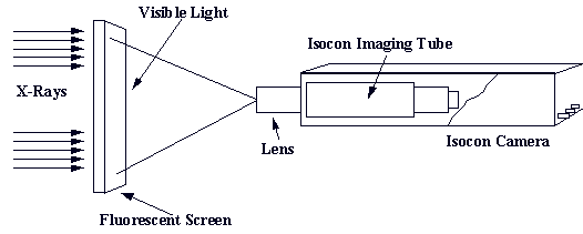
Figure 1: Typical "Flat Screen" Imaging Arrangement
- Computer Processing Speeds. Processing systems to capture, manipulate and analyze an entire tire image (usually 15 – 50 Mbytes) were prohibitively expensive.
- Tire Building Techniques. Tire building techniques were sufficiently dependent upon tire builder skills that X-ray analysis of the complex tread package was needed and this represented an extremely difficult challenge for X-ray analysis.
Today the majority of the technical measurement difficulties have been overcome through the combination of new X-ray imaging technology and very high-powered industrial PCs. Additionally, newer methods of tire building have significantly reduced the need to examine detailed inner tread-package areas of the tire’s construction.
Many years of experience in automatic inspection systems have repeatedly demonstrated a fundamental precept. High reliability automatic inspection can only be achieved when the images of the product being inspected are of the highest quality. Additionally, high-speed automatic inspection can only be achieved when significant dedicated computer power can be easily (affordably) brought to bear on the automatic inspection process. Typically the job of automatic inspection relies on 50% imaging and 50% effective processing.
Today’s technologically advanced linear diode array imaging system is a specially designed 1,536 pixel, high resolution, wide dynamic range system physically configured to match the shape of a tire. (See figure 2.) Automatic X-ray inspection of tires is a natural outgrowth of the design of this advanced imaging system which provides the high quality X-ray imaging platform required for automatic inspection of tires.
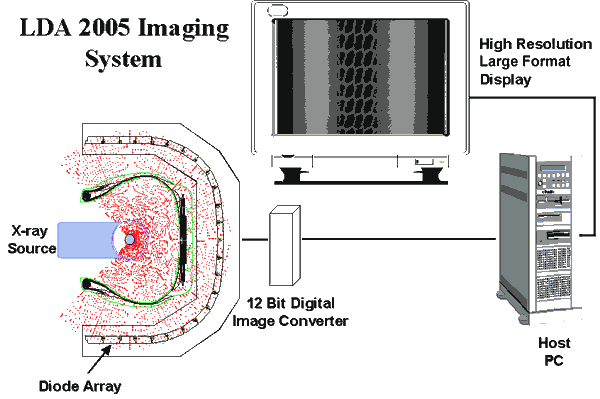
Figure 2: Linear Diode Array Imaging System
Past tire X-ray inspection systems required three rotations of the tire to gather information necessary to generate an image. The image was then generated in three sections: upper sidewall, tread, and lower sidewall with each section presented on a separate monitor. Today, information is collected in a single pass, and the complete image can be presented on a single high-resolution monitor. The same digital information used to produce the composite image is also sent to a computer for evaluation.
Until the linear diode array imaging system was available, inspection algorithms based on the output of traditional frame-based imaging systems were limited to 8-bit pixel depth (versus 12 for the linear diode array) which severely limited the dynamic range available. Any adjustment of individual picture elements to correct for varying imaging conditions was impracticably complex.
Elements of the linear diode array are individually offset and gain corrected. Geometric distortion is also reduced in the system because the array is shaped to approximate the contour of a tire from bead to bead. In addition, since the tire image can be gathered in a single pass, the only requirements of the tire handling system are that same type tires be presented in the same orientation and that the imaging process is synchronized to tire rotation speed.
The initial implementation of the tire automatic X-ray inspection package is targeted at steel radial truck/bus tire inspection. There are a number of reasons for this:
- Steel radial tires are generally of single body ply construction. This means a defect in the ply is much more serious than a defect in one ply of a multi-ply.
- Steel in rubber yields high contrast X-ray images which are much easier to analyze.
- Steel radial tires are the highest cost tires and therefore the tires for which customers have the highest quality expectations.
- Steel radial construction has been increasing steadily as a percentage of overall truck and bus tire production. In the United States, steel radial construction as a percentage of overall truck and bus tire production is now well in excess of 90% of all production.
The automatic X-ray inspection package eliminates the need for the inspector/operator to subjectively interpret an X-ray image to make a pass/fail decision. Instead, it uses the digital tire X-ray image captured by the linear diode array imaging system. The image is passed to a computer where it is examined for cord, tread package, turn-up and bead anomalies. If an anomaly is detected, the tire is marked (or shunted), and the image is saved for a final off-line review.
Based on current production figures, it is estimated that 10 – 20 % of total production will require review thus reducing inspection labor from 24 hours in a 24-hour day to 2 ?to 5 hours per day. This reduces inspection labor to approximately 1/6th the current level. Inspection review can be accomplished on a single shift and usually as a secondary or fill-in task. Additionally, the inspection review process can be interrupted without adversely impacting production flow.
Automatic X-ray inspection test specifications can be adjusted to the tire manufacturer’s desired level for each type of tire being inspected. The system will consistently inspect tires for deviations from that level to a much closer tolerance than can be achieved by rapid human subjective inspection.
It is anticipated this can reduce rejection levels by 0.1% in situations where the human operator typically rejects 0.5% of production. Therefore, for example, a 0.1% improvement on returned tires for a plant building 6,000 tires per day for a $300 truck tire is $630,000/year.
Because automatic X-ray inspection consistently inspects each tire regardless of the number of units inspected, the occasional false accept of a radical defect is virtually eliminated.
There are five basic criteria which drive the automatic X-ray inspection system architecture and the anomaly detection algorithms. These are:
- Ease of setup and implementation
- Consistency of presentation
- Representation of tire characteristics by discrete area analysis
- Feasibility of post inspection review of suspect tires
- Ability to complete the image analysis during the unload cycle.
Ease Of Setup And Implementation
During the "teaching" phase, type of test, test specifications, regions of interest, and relational measurement references are established for each type of tire that will undergo automatic inspection. (See figure 3.) These parameters (along with the image of the setup tire) are saved to a reference "recipe" database. (See figure 4.) Subsequent automatic inspections use the parameters appropriate to the current tire based solely on the "recipe number" transmitted as part of the tire image file. During the "teaching" phase, the operator is able to interactively test and adjust the setup parameters.
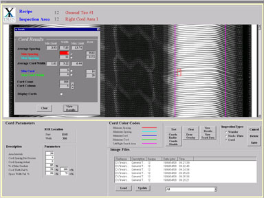
Figure 3: Setup/Teaching Screen
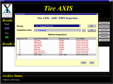
Figure 4: Recipe/Inspection List
Consistency of Presentation
Reliable and efficient inspection requires a few limitations on the tire manipulator and imaging system. These are: same type tires must be presented in the same orientation, rotated at the same speed, and imaged using the same X-ray and linear diode array settings as the setup tire for that product code (recipe number).
Representation Of Tire Characteristics By Discrete Area Analysis
To detect the majority of tire anomalies, it is sufficient to analyze discrete 360?columns of the tire image as representative of the whole tire. For example, it should not be necessary to analyze each vertical column of image data to test for cord thickness and spacing deviations in the sidewall. This assumption is a derivative of the subjective inspection technique used by tire inspectors today who view images from traditional tire X-ray inspection systems. In each case, the operator concentrates on the moving image in such a way that the eye catches deviations from the average such as changes in cord spacing, belt wander, bead protrusions, dog-eared splices, etc. (See figure 5.)

Figure 5: Anomaly Detected
Feasibility Of Post Inspection Review Of Suspect Tires
The automatic X-ray inspection system is configured to automatically inspect a sequence of tires. When an anomaly is detected which exceeds the thresholds defined at setup for that tire type, the following sequence occurs.
- The complete tire image along with information about the type and location of the detected anomaly are saved to a database.
- The tire is either marked as anomalous or it is diverted, as it leaves the test chamber, to a special storage rack which holds tires with suspected anomalies in the same sequence in which they were detected and the image was stored.
- An operator then reviews and/or re-analyzes the suspect tire images either on the local system (inspection off-line) or from an off-line system which presents the advantage of not affecting the ongoing inspection process.
This process allows the detection limits to be set to sufficiently tight tolerances that false accepts are negligible at the expense of creating false rejects. With sufficient history, the detection limits can be adjusted to allow virtually total automatic operation.
Ability To Complete The Image Analysis During The Unload Cycle
The automatic X-ray inspection system utilizes the resources of a high speed image processing system to guarantee that analysis of the image from even the largest tire is completed before the tire reaches the exit station. Typical tire inspection cycle times of 30 seconds or less are realizable while making a broad range of inspections on the complete tire.
The automatic X-ray inspection system will perform tests on the bead area, turnup, sidewall cords, and belt edges.
Body cord is examined from the edge of the tread belt package to the turnup or chaffer. Automatic X-ray inspection provides a minimum of 20 inspection columns on each sidewall. The average cord spacing and cord diameter is computed for each column. The average spacing of each inspection column is compared to the average of the remaining columns. Deviations greater than one cord diameter (or greater if selected in setup) cause an anomaly identification. Among the sidewall anomalies the automatic X-ray inspection system can discern are wide cords (doubled), wide spaces, narrow cords, missing cords (broken), and foreign material.
Belt and turnup tests detect wander as well as snaking, scalloping, necking, and flare.
Testing of the bead area includes loose wires and gross weld faults.
In summary, automatic X-ray inspection of tires is now feasible and commercially available. The enabling technologies are economical yet powerful computing systems and high-resolution, high-dynamic range X-ray imaging systems customized for tire inspection. The key advantages of reduced inspection labor, highly consistent inspection and yield improvement are now realizable.
[technical_articles_selections_tab.htm]