ISONIC MIA Bond Mapping System
Principles of Operation
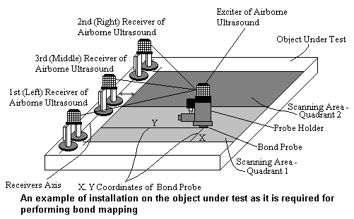
ISONIC principles of operation may be better understood with reference to above Block Diagram and an example of installation on the object under test as it is required for performing bond mapping:
| An operator clamps bond probe into the probe holder, which is a handheld implement for manipulation. The operator grips probe holder and applies bond probe to object under test. Operator guides bond probe over scanning area | |
| Probe holder is equipped by exciter of airborne ultrasound, which emits pulses of ultrasonic energy into the air. There are three receivers of airborne ultrasound attached to the object under test and aligned near the scanning area. ISONIC is determining the coordinates of bond probe through measuring travel times of airborne ultrasonic pulses detected by said receivers | |
| Probe holder is equipped with detector of coupling between bond probe and object under test. ISONIC generates an image of actual probe trace by correlating between bond probe coordinates and coupling condition | |
| ISONIC generates images of defects on the background of probe trace image according to output signal of bond tester and current location of bond probe | |
| ISONIC provides storing, representing, postprocessing and documenting for all measured and imaged data |