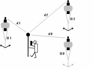
 Figure 1: A Long Baseline
Configuration Consists Of Baseline And Mobile Stations
Figure 1: A Long Baseline
Configuration Consists Of Baseline And Mobile Stations Granted, some underwater navigation tasks really don’t require much accuracy. If you are piloting a ROV it may be quite sufficient to have a general idea as to where the vehicle is. Not so when it comes to mapping artifacts, marine creatures or bottom composition. Here the difference between a system that gives you pretty good positions and one that puts you right on the spot may be the difference between a very expensive boat anchor and a truly useful tool.
As a manufacturer, we would like to claim a single, firm number for navigation accuracy. However, in reality accuracy depends on many factors. The good news is that precision DiveTracker series systems such as AquaMap can actually yield data that is much better than even our best data sheet claims of +/- 0.15 meters. On the other hand, the wrong system configuration or improper use may leave you coping with sloppy results. In short, if accuracy is your game, you have got to know how the system works, what its limits are and how to deal with them.
This paper will give you a good idea what to expect. After reading it
you should be able to judge if the system will meet your requirements and what it takes to
get the job done.
In order to understand what limits accuracy, it is first necessary to understand just how precision underwater navigation works.
DiveTracker systems include of a ‘surface station’ and/or a
number of ‘baseline stations’. These stations serve as the reference points for
navigation. For high accuracy work, our AquaMap ‘long baseline’ configurations
such as the one shown in figure 1 are used. The configuration employs three baseline
stations (B0, B1, B2) as the reference for navigation. Our model RBS-1 and RBS-2 baseline
stations are self contained cylinders equipped with syntactic foam flotation collars.
Anchored by a line to the ocean floor, each baseline station is secured such that it
floats in the water column well below the surface. Buoyed by its flotation collar, it
works as a stable ‘underwater antenna tower’, providing a precise reference
position.
Figure 1: A Long Baseline
Configuration Consists Of Baseline And Mobile Stations
The diver, ROV or AUV (generically known as mobile station) carries a transponder such as our model DS-1 for divers. To find its current position, the transponder sends a sonar interrogate signal. The signal travels through the water and is eventually received by the baseline stations. Upon reception of the interrogate, each baseline station transmits a reply. The replies from each baseline station travel back to the mobile station. By measuring the time elapsed between the transmission of the interrogate and the reception of the reply, the mobile station can compute its current distance from each baseline station (d0, d1, d2). A little trigonometry and the knowledge of its own depth and the depth and position of each baseline station are then used by the mobile station transponder to compute its own position. How does the mobile station know the position and depth of the baseline stations? The relative positions of the baseline stations are determined by the mobile station through a similar series of sonar interrogates and replies prior to the survey. In some rare cases, baseline station positions may also be surveyed by some independent means and ‘told’ to the system.
Sonar position fixes are always relative to the network of baseline stations or surface station transducers. In the above example, we define the location of B0 to be the origin of our coordinate system. The ‘X’ axis runs from B0 through B1, and the ‘Y’ axis is at a right angle to that ‘X’ axis. If you need to know an underwater position in latitude and longitude, it is necessary to tell the system the position and orientation of the baseline network. This can be done manually by entering coordinates or by linking the DiveTracker system to a GPS receiver.
Note: The above described method of finding a position is just one of
many ‘pinging protocols’ used by DiveTracker to fix positions. Different
protocols have different characteristics. As a system user, you don’t have to worry
about pinging protocols. If you are a student of that matter however, call us for more
information.
Positioning ‘accuracy’ really has two components, namely accuracy and repeatability. Repeatability describes how consistent the position fixes are. If you have found a treasure chest on the ocean floor, you need a navigation system with good repeatability to guide you back to that chest. Accuracy describes how close a position fix is to the actual position. Accuracy is needed in order to properly correlate a position fix with a position on a chart. The mariner needs high accuracy in order to find a harbor entrance or other location published on a chart. Thus, a position fix can at the same time be very repeatable but not very accurate.
The following list describes what factors determine positioning accuracy and repeatability.
AquaMap precision ‘long baseline’ systems use baseline stations as the reference points for navigation. Any position fix is only as good as the stability of the baseline stations. If a baseline station swings back and forth one meter due to surge or current, don’t expect your position fixes to be any better than that.
‘Short baseline’ configurations use boat mounted surface station transducers rather than sea floor anchored baseline stations. This means, all position fixes will be referenced to the location of the surface vessel, and not the sea floor. If sea floor referenced positions are required, your position fixes will only be as good as the knowledge of the location and orientation of the surface vessel. As surface station position is usually determined by a differential GPS receiver and heading sensor connected to the DiveTracker system, any underwater position will only be as good as the quality of the GPS and heading sensor fixes.
The repeatability of any position fix is limited by the consistency with which DiveTracker measures the distance between a mobile station and the baseline or surface station transducers. The accuracy of the position fix is limited by the system’s ability to estimate the speed of sound. If speed of sound is underestimated, distances will appear shorter than they really are and vice versa.
Both repeatability and accuracy are also dependent on the geometry of the baseline. In general, best position fixes are obtained when there are two baseline stations that appear to be roughly at right angles from the vantage point of the mobile station. If the baseline stations are either very close together or if all baseline stations are about in the same direction, accuracy is at its worst. The problem is somewhat similar to taking sightings of land marks to fix your position at sea. For best results, you will always choose landmarks that appear in different directions.
The distance between stations affects accuracy and repeatability. Sound rarely travels in a perfectly straight line. The distortions of the sound path become greater, resulting in reduced accuracy, as it covers greater distances.
Finally, accuracy but not repeatability is affected by the precision of the baseline station position survey. Your position fixes will contain an accuracy error that reflects the error of the baseline survey.
Looking at this list, you may wonder if you will ever obtain a precision
position. Don’t worry! By following a few simple rules, you can obtain excellent
results. Read on to find out how it’s done.
For the most part, getting high quality data is a matter of properly deploying and setting up a system. In surgy conditions, equip baseline stations with extra buoyancy to keep them stable in the water column. If that isn’t enough, mount the baseline stations on a rigid underwater structure. Mount three baseline stations near the corners of a rectangular survey area. This will ensure good geometry (two stations at approximately a right angle to each other) no matter where you are. Keeping your survey areas small will prevent errors due to long sonar signal paths.
You won’t have to worry about sound speed estimation errors. Sound speed is quite well defined as a function of sea water temperature, salinity and pressure (depth). DiveTracker directly measures temperature and depth. You tell the system the salinity of the water. This information is used to estimate sound speed with an error of around 0.005% (5 cm at 1 km range).
Work in the field has shown that a repeatability of about 15 cm (RMS error) can be obtained when the above rules are followed and the stations are spaced no more than about 100 meters apart. As station distance increases to 500 meters, we have seen position repeatability of around 60 cm to 100 cm. DiveTracker has been tested in deep and shallow waters, in calm seas, near surf zones and during storms. With the exception of baseline station movement, none of these conditions has ever had a measurable effect on repeatability.
Confirming the accuracy of the system is a bit harder as it requires an independent and more accurate survey method. On one occasion, we had the opportunity to confirm the positioning of underwater monuments (railroad wheels) that a land based surveyor had positioned to an accuracy of 30 cm before they were dropped from a boat into the water. The spacing between the monuments was from 120 to 240 meters.
DiveTracker measured the location of these monuments to be within less than 60 cm of their target position. Given the error inherent in the surveyor’s work along with any possible sideways movement of the wheels as they dropped to the ocean floor, the measured error was within the ‘noise’ of the monument deployment itself.
In summary, AquaMap long baseline systems can be used with little effort
to yield positioning accuracy and repeatability well within the sub-meter region. This
accuracy is quite sufficient for much work such as the plot in figure 2 showing the height
of waste deposits on the ocean floor which was generated by Enviro-Tech Diving of Seattle.
If this level of accuracy is sufficient for your job, you may just as well skip the rest
of this paper. If you are looking for centimeter performance however, take a look at the
next chapter. 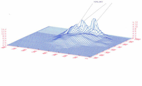 Figure 2:
Sub-Meter Positioning Accuracy Was Sufficient To Map These Sea Floor Waste Deposits
Figure 2:
Sub-Meter Positioning Accuracy Was Sufficient To Map These Sea Floor Waste Deposits
Assuming a good geometry, proper sound speed estimation and no movement of baseline stations, the last major factor defining positioning quality is the repeatability of sonar range measurements.
There is an inherent limit to that repeatability which is set primarily
by DiveTracker’s method of detecting incoming sonar signals. Our data sheets
conservatively claim that error to be 15 cm RMS (mean deviation). However, actual testing
done by both us and other parties has consistently found the error to be much smaller.
Figure 3 shows a set of range measurements at a station separation of 552 feet (168 m).
For the test, two DiveTracker stations where set up on the floating dock at Moss
Landing’s North Harbor. DiveTracker measured the station separation 175 times. The
plot graphs the result. The range is indicated in feet. The mean deviation (RMS error) of
this test series was 0.19 feet (5.8 cm). Test series over shorter distances which were
taken the same day yielded similar results. 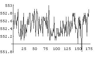 Figure 3: 175 Successive Range Measurements Of Two DiveTracker Stations
Placed 552 Feet Apart
Figure 3: 175 Successive Range Measurements Of Two DiveTracker Stations
Placed 552 Feet Apart
A cursory look at the data suggests that the distribution of RMS errors among the range samples is random. This characteristic can be used to further improve data quality by averaging multiple range samples.
Figure 4 shows the effect of averaging on data quality. The graph is
derived from a data set containing 3000 range samples, the test range was 151 feet.
Indicated on the ‘X’ axis is the number of samples that were averaged. The
‘Y’ axis shows the corresponding RMS range error expressed in feet. At a sample
size of 1, this data set exhibits an RMS error of 0.235 feet (7.16 cm). When averaging the
same data over 100 samples, the error decreases to 0.079 feet (2.41 cm). Averaging over
more than 100 samples resulted in only gradual improvements. 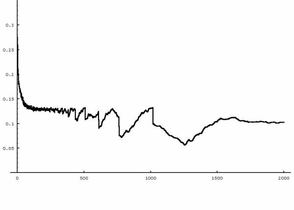 Figure 4: A Marked Improvement In Data Quality
Can Be Obtained By Averaging Several Range Samples
Figure 4: A Marked Improvement In Data Quality
Can Be Obtained By Averaging Several Range Samples
Once more, tests done that day over other (short) ranges and signal paths yielded
similar results. The test data shows that by averaging multiple samples, a range
repeatability of 4 cm or less can be obtained. Using proper baseline station geometry,
positions can be fixed with similar accuracy. However, the user must keep in mind that the
improved data quality is paid for with a time penalty. Acquiring 100 position fixes takes
about two minutes when baseline stations are spaced 300 feet (100 m) apart. Greater
separations will result in longer acquisition times.